I-V (CURVE TRACE) MEASUREMENT
I-V (Curve Trace) Measurement
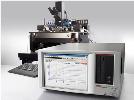
An I-V curve tracer measures an I-V relationship of an electrical device during transient conditions. In operation, the curve tracer couples across the device a fixed-value inductive or capacities load. While the current and voltage flowing through the device approach steady-state levels, the voltage and current are sampled and stored in a memory upon predetermined incremental changes in one parameter of the device such as voltage.
A digital representation of one parameter, such as voltage, constitutes a memory address and another parameter, such as current, is stored at that address in the memory. A data processor subsequently retrieves the memory data and addresses to display or plot the I-V relationship of the device. This parametric sampling technique assures that the measurements are coincident in occurrence with the sweeping of the I-V curve and eliminates the need for complex control and timing circuits.
What is a Curve Trace?
A curve trace is produced by an electrical test that usually measures the current (I) that results from applying a voltage (V) varied over a range from one voltage value to another value.
A curve trace measurement is made using a curve tracer, parameter analyzer, or other electrical test equipment. This type of test is typically performed at a bench setup to complement automatic test equipment (ATE) data or replace it when ATE testing is not feasible. The display or plot of current versus voltage obtained from this test is referred to as a curve trace or I-V measurement. Curve traces can also be V-V or V-I measurements or even V vs. time or I versus time if necessary.
Curve trace measurements can provide insight into numerous failure mechanisms that can affect the I/O pins, including EOS, ESD, bond wire problems, and packaging problems. Another advantage of curve tracing is its ease of setting up, low cost, non-destructive nature, and flexibility.
optical microscopy failure analysis • ic decapsulation service • Counterfeit Component Authenticity • Cross Section Analysis • Parallel Lapping • Energy Dispersive X-Ray Spectroscopy • Focused Ion Beam • Photoemission microscopy failure analysis • Scanning Acoustic Microscopy • electron microscope services • Secondary Ion Mass Spectrometry • IC X-Ray services